經(jīng)銷品牌

你的位置:首頁 » 產(chǎn)品中心 » Former(二手)儀器 » 網(wǎng)絡(luò)分析儀 » E8362B PNA Network Analyzer, 10 MHz to 20 GHz---徐經(jīng)理 18912657535
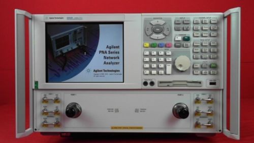
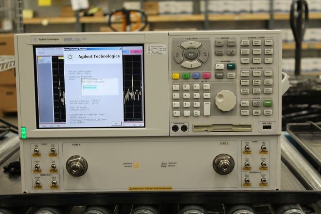
儀器名稱: E8362B PNA Network Analyzer, 10 MHz to 20 GHz---徐經(jīng)理 18912657535 儀器型號(hào): Agilent E8362B 2port 20 GHz 儀器品牌: Agilent 儀器指標(biāo): 2port 10 MHz to 20 GHz
Key Features & Specifications
- 123 dB dynamic range and <0.006 dB trace noise
- <26 usec/point measurement speed, 32 channels, 16,001 points
- TRL/LRM calibration, on-wafer, in-fixture, waveguide, and antenna measurements
- Mixer conversion loss, return loss, isolation, and absolute group delay
- Amplifier gain compression, harmonic, IMD, and pulsed-RF .
Description
General-purpose network analysis with optional software and/or hardware to customize for your application - such as multiport, pulsed-RF, etc.
View: PNA Series Video Demos
Discuss calibration, applications, programming topics: Network Analyzer Discussion Forum
Support: PNA Series Service & Support
PNA Series Network Analyzer
The microwave PNA Series instruments are integrated vector network analyzers equipped with a built-in S-parameter test set, synthesized source, a hard disk drive, USB interfaces, and an 8.4” LCD color touch screen display. The E8362C has 3.5 mm male 50-ohm test ports. The E8363C/64C have 2.4 mm male 50-ohm test ports. The E8361C has 1.85 mm male 50-ohm test ports. Included with each instrument is a mouse, keyboard (U.S.) and a 1-year return-to-Agilent service warranty.
Test set and power configuration options
□ Configurable test set (Option 014)
Provides six front panel access loops. Three access loops are for port one and three for port two. The loops provide access to the signal path between (a) the source output and the reference receiver, (b) the source output and directional coupler thru arm and (c) the coupled arm of the directional coupler and the port receiver. This option provides the capability to improve instrument sensitivity for measuring low-level signals, to reverse the directional coupler to achieve even more dynamic
range or to add components and other peripheral instruments for a variety of measurement applications. (see PNA Series Microwave Data Sheet literature number 5989-7605EN for a basic block diagram)
□ Extended power range and bias-tees (Option UNL)
Adds two 60 dB step attenuators and two bias-tees to the E8362/3/4C. Adds two 50 dB step attenuators and two bias-tees to the E8361C. A step attenuator and bias-tee set is inserted between the source and test port one and another set between the source and test port two. (see PNA Series Microwave Data Sheet literature number 5989-7605EN for a basic block diagram)
□ Add receiver attenuators (Option 016)
An attenuator is added between each test port and its corresponding receiver. Two 35 dB step attenuators are added to the E8362/3/4C. Two 50 dB step attenuators are added to the E8361C (see PNA Series Microwave Data Sheet literature number 5989-7605EN for a basic block diagram).
□ High-power test set (Model E836xCH85)
This configuration combines options that are often necessary for high power measurements (UNL1, 014, 016, 080, 081). The only difference between ordering Option H85 versus a
combination of the options listed above is the source attenuator option UNL. Standard UNL includes two source attenuators and two bias-tees. Option H85 includes the two source attenuators, but not the bias-tees, as the bias-tees are the power-limiting factor in the network analyzer test set. The maximum power at the test port is +43 dBm (< 20 GHz), and
+40 dBm (> 20 GHz).
Option 080, frequency-offset mode, is included in Option H85 because it manages the phase-locking internally (instead of depending on the R1 receiver). So if you need to use external components in the path of the R1 receiver, it makes the measurements simpler and more robust.


